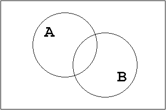
Figure 1.19: Commutative Law.
| Contents | Previous Chapter | Next Chapter |
The Boolean function will now be treated in more detail, especially the two-valued Boolean algebra will be defined more precisely.
For this purpose in principal two different options are available: starting with what is called the lattice theory or with a system of axioms. The axiomatic approach will be preferred here, using a system that the American mathematician E.V.Huntington developed in 1904.
When applying the axiomatic system a differentiation can be made between so-called
The postulates are fundamental axioms, the theorems have to be proven from these postulates.
The Boolean postulates are formally defining the requirements that a Boolean algebra must fulfil.
Definition:
The Boolean algebra is the set A of elements 0 and 1, in which the two-valued operations
"+" and "•" are defined, so that the following is valid:
On the basis of the Boolean postulates the Boolean theorems (laws) can now be defined. The correctness of these laws can be verified at any time using the postulates (e.g. applying Venn-diagrams or truth tables).
A theorem in the Boolean algebra is a rule (law), that expresses a fundamental relationship between the Boolean variables. Applying the theorems will then allow the manipulation and simplification of logical circuits.
To define and discuss the individual theorems three aspects will be looked at:
T1: Commutative Law
T1.1
| a) | a + b = b + a | |
| b) | a • b = b • a |
T1.2 Set Presentation:

Figure 1.19: Commutative Law.
Plausibility consideration:
Obviously it does not make any difference in which order the sets A and B are combined disjunctively ("+") or conjunctively ("•").
T1.3 Gate-level Implementation:

Figure 1.20: Commutative Law on Gate-Level.
Plausibility consideration:
Obviously it does not make any difference in which order the input variables are applied to the OR or AND gates, respectively
T2: Associative Law
T2.1
| a) | (a + b) + c = a + (b + c) | |
| b) | (a • b) • c = a • (b • c) |
T2.2 Set Presentation:
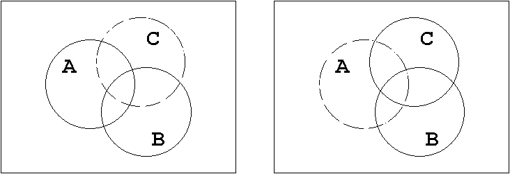
Figure 1.21: Associative Law.
Plausibility consideration:
Obviously it does not make any difference in which order the sets A, B, and C are combined disjunctively ("+") or conjunctively ("•").
T2.3 Gate-level Implementation:
Each bracket term in the algebraic form corresponds to a gate level in the gate-oriented implementation (the corresponding algebraic expression is also called "gate isomorphous").
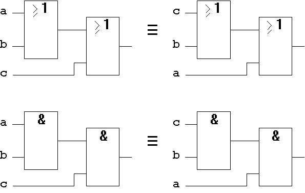
Figure 1.22: Associative Law on Gate-Level.
T3: Distributive Law
The functions "disjunction" and "conjunction" are distributive, i.e. "OR" is distributive over "AND", "AND" is distributive over "OR".
T3.1
| a) | a + (b • c) = (a + b) • (a + c) | |
| b) | a • (b + c) = (a • b) + (a • c) = a • b + a • c |
Using propositional logic this means in case of a):
the expression "a + (b •
c)" is true when "a" is true or when "b" and "c" are true.
"(a + b) • (a + c)" is true when both bracket terms are true. These expressions in turn are true when "a" is true.
In case that "a" is not true, both - "b" and "c" - must be true.
Similarly the algebraic form b) can be interpreted.
T3.2 Set Presentation:
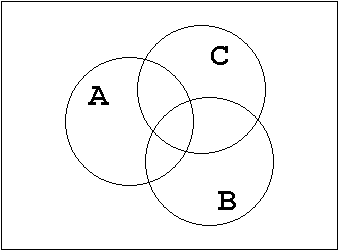
Figure 1.23: Distributive Law.
Plausibility consideration:
Using a step by step approach to build up the set diagram the correctness of the Distributive Law
can be shown.
T3.3 Gate-level Implementation:
Applying this theorem T3 the number of gate inputs (the so-called pin count) of a circuit can be reduced.
Version a):
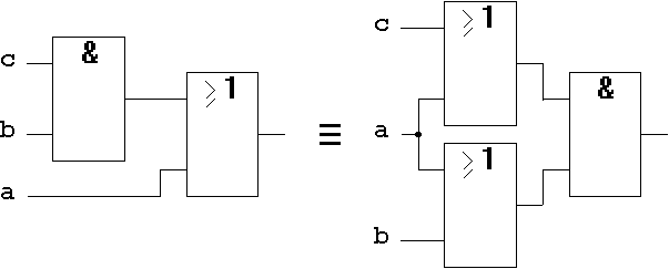
Figure 1.24: Distributive Law on Gate-Level.
For version b) the gate-level implementation can be done in similar form.
T4: Indentity Law (Idempotency Law)
T4.1
| a) | a + a = a | |
| b) | a • a = a |
T4.2 Set Presentation:
The set remains unchanged when combined disjunctively or concunctively with itself.
T4.3 Gate-level Implementation:

Figure 1.25: Identity Law on Gate-Level.
The circuit is logically redundant. But it causes a delay for signal "a" and therefore has technical importance.
T5: Absorption Law (Redundancy Law)
T5.1
| a) | a + (a • b) = a | |
| b) | a • (a + b) = a |
Using propositional logic this means:
for the expression "a + (a • b)":
is "a" true, then the value of "b" is
irrelevant. But when "a" is false, then (a • b) cannot be true. Obviously the expression is totally determined by "a", "b" gets "absorbed".
for the expression "a • (a + b)":
is "a" true, then "(a + b)" will also be true, i.e. the entire expression will be true. Is "a" false then the entire expression will be false. Obviously the expression is totally determined by "a" again, "b" gets "absorbed".
This law results directly from the Distributive Law and the Identity Law (T3 und T4).
T5.2 Set Presentation:
The logical redundancy of the circuit can easily be verified with the Venn-Diagram.
T5.3 Gate-level Implementation:
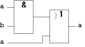
Figure 1.26: Absorption Law on Gate-Level.
The circuit is logically redundant. But as will be seen later, this circuit will delay the signal "a" by two gate delays and therefore has a technically relevant function.
T6: Zero- and One-Law
T6.1
| a) | 0 + a = a, 1 + a = 1 | |
| b) | 0 • a = 0, 1 • a = a |
T6.2 Set Presentation:
The verification of this theorem using Venn-Diagrams is trivial..
T6.3 Gate-level Implementation:
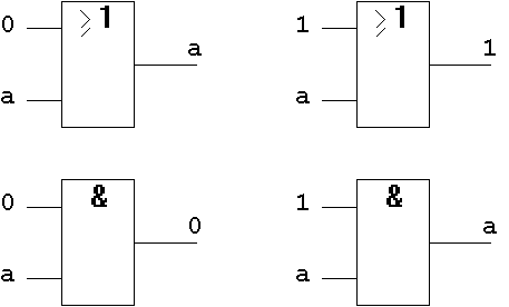
Figure 1.27: Zero- and One-Law on Gate-Level.
T7: Complement Law
For every element "a", there exists a complement element "\a".
"\a" is called the complement of "a".
T7.1
| a) | a + \a = 1 | |
| b) | a • \a = 0 |
T7.2 Set Presentation:
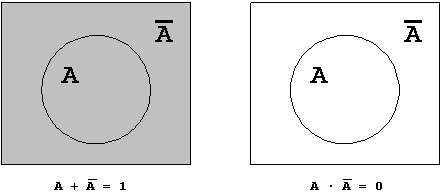
Figure 1.28: Complement Law.
T7.3 Gate-level Implementation:

Figure 1.29: Complement Law on Gate-Level.
T8: De Morgan Theorem
T8.1
| a) |  |
|
| b) |  |
The de Morgan Theorem has very high importance for circuit design. Especially for the transformation of circuits, this law shows the possibilty to interchange so-called dual Boolean Functions.
As the algebraic forms above show, the transformation of NOR to AND circuits and NAND to OR circuits is directly possible.
NOR → AND
NAND → OR .
This can easily be seen from the gate-level Implementation:
T8.3 Gate-level Implementation:
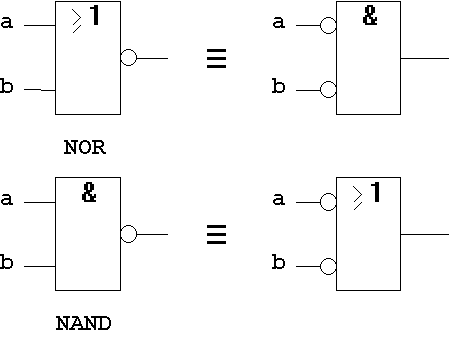
Abb. 1.30: De Morgan Theorem on Gate-Level.
| Contents | Previous Chapter | Next Chapter |